728x90
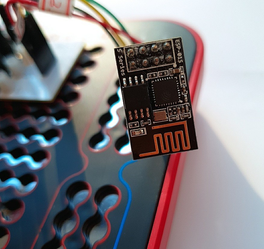
Arduino ESP8266
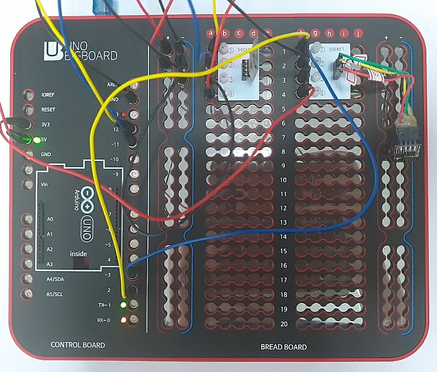
아두이노와 ESP8266을 이용하여 와이파이 TCP 통신을 구현합니다.
Node-RED 데이터 송수신을 구현합니다.
먼저 아두이노 스케치에서 프로그래밍을 진행합니다.
SoftwareSerial을 이용하여 ESP8266과 시리얼 통신 오브젝트를 생성합니다.
#define RXPIN 3
#define TXPIN 2
SoftwareSerial esp8266Serial(RXPIN,TXPIN);
// Pin 2 & 3 of Arduino as RX and TX. Connect TX and RX of ESP8266 respectively.
ESP8266 AT COMMAND 전송 문자열 과 결과값 디버그 출력합니다.
String esp8266Data(String command, const int timeout, boolean debug)

  {

	if (debug)
    {
		Serial.print("CMD: ");
      Serial.println(command);
    }

    String response = "";
    esp8266Serial.print(command);
    long int time = millis();
    while ( (time + timeout) > millis())
      {
        while (esp8266Serial.available())
          {
            char c = esp8266Serial.read();
            response += c;
          }
      }
    if (debug)
    {
      Serial.print(response);
    }

    return response;
  }
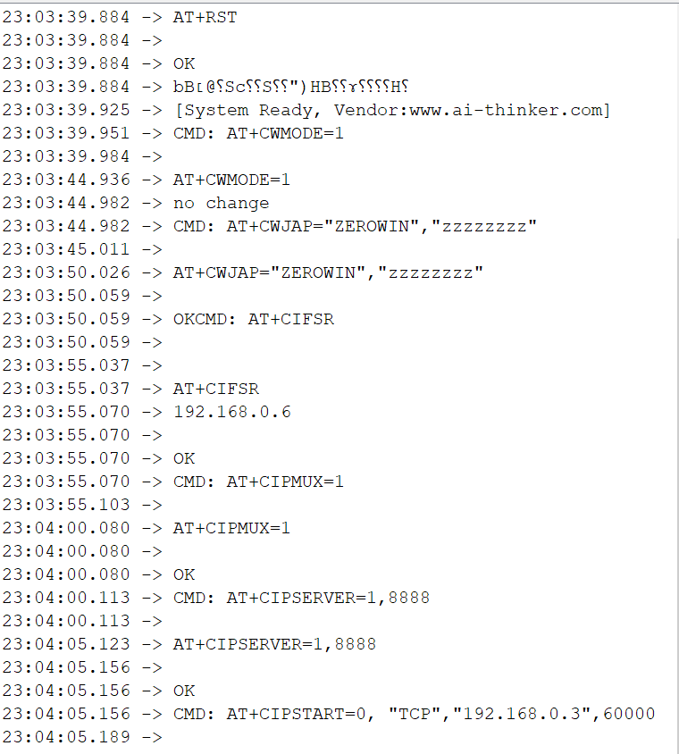
setup 함수에서 esp8266 초기화합니다.
그리고 tcp 소켓 8888 열어 tcp 데이터를 수신할 수 있게 설정합니다.
esp8266Serial.begin(9600);
  esp8266Data("AT+RST\r\n", 5000, DEBUG); // Reset the ESP8266
  esp8266Data("AT+CWMODE=1\r\n", 5000, DEBUG); //Set station mode Operation
  esp8266Data("AT+CWJAP=\"ZEROWIN\",\"zzzzzzzz\"\r\n", 5000, DEBUG);//Enter your WiFi network's SSID and Password.
  esp8266Data("AT+CIFSR\r\n", 5000, DEBUG);//You will get the IP Address of the ESP8266 from this command.
  esp8266Data("AT+CIPMUX=1\r\n", 5000, DEBUG);
  esp8266Data("AT+CIPSERVER=1,8888\r\n", 5000, DEBUG);
Node-RED로 전송할 tcp 소켓을 생성합니다.
void OpenSession()
{
   // esp8266Data("AT+CIPSTART=\"UDP\",\"192.168.0.3\",50000\r\n", 5000, DEBUG);
   esp8266Data("AT+CIPSTART=0, \"TCP\",\"192.168.0.3\",60000\r\n", 5000, DEBUG);
   bConnected = true;
   return;
}


void CloseSession()
{
   esp8266Serial.println("AT+CIPCLOSE=0");
   return;
}
loop 함수 안에서 Node-RED 로 데이터를 전송합니다.
void loop(void)
{
	  sprintf(sendData, "VALUE, %d, %d", cdcValue, waterValue);

      SendToClient(sendData);
}


String readStr, writeStr;

void SendToClient(String s)
{
    writeStr = s;
    //Serial.println("\nAT+CIPSEND=" + String(writeStr.length() + 2));
    //delay(100);
    esp8266Serial.println("AT+CIPSEND=0," + String(writeStr.length() + 2));


    // Serial.print(millis()); Serial.print("= ");
    String result = "";
    char ch = 0x00;

    while(ch != 0x00)
    {
      if(0 < esp8266Serial.available()) {
         ch = esp8266Serial.read();
         result += ch;
     }
     delay(1);

    };

    Serial.print("result=");
    Serial.println(result);
    //readStr = esp8266Serial.readString();
    //Serial.print(readStr);

    delay(10);

    //Serial.println("\n" + writeStr +"\n\r");
    esp8266Serial.println(writeStr);
    return;
}
TCP 데이터를 수신합니다.
String result2 = "";
        while(0 < esp8266Serial.available()) {
           char ch = esp8266Serial.read();
           result2 += ch;
        }
      Serial.print("result2=");
      Serial.println(result2);


      int firstListItem = result2.indexOf("link is not");

      if(firstListItem != -1) {
        CloseSession();
        delay(100);
        OpenSession();
      }

      else {

        // +IPD,12:1023,681,310

        firstListItem = result2.indexOf("+IPD");
        if(firstListItem != -1) {
          firstListItem += 5;

          int secondListItem = result2.substring(firstListItem).indexOf(":");
          if(secondListItem != -1) {

            String dataLen = result2.substring(firstListItem, firstListItem + secondListItem);
            int len = dataLen.toInt();

            Serial.print("dataLen=");
            Serial.println(dataLen);

            String data = result2.substring(firstListItem + secondListItem + 1,
            firstListItem + secondListItem + 1 + len);

            Serial.print("data=");
            Serial.println(data);

          }

        }

      }
시리얼모니터 디버깅 화면
esp8266 설정시
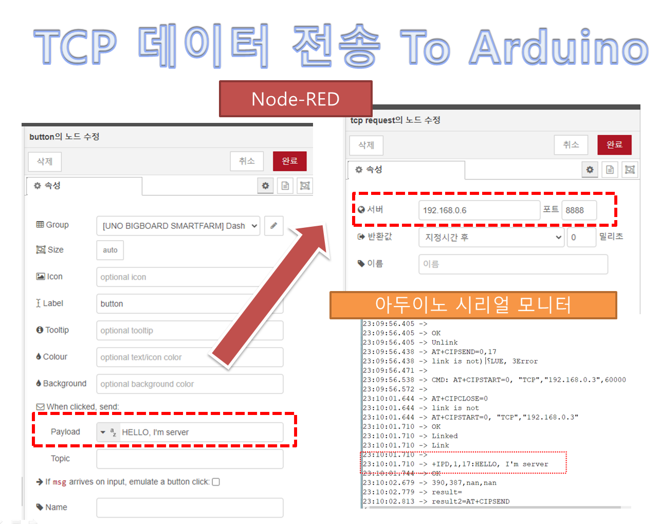
Node-RED
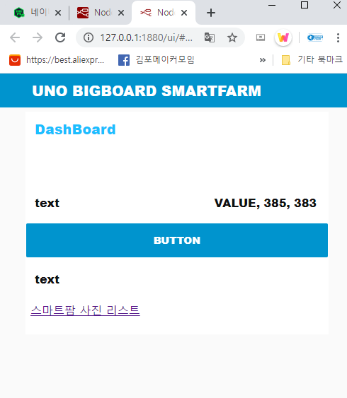
버튼을 누르면 아두이노로 데이터를 송신합니다.
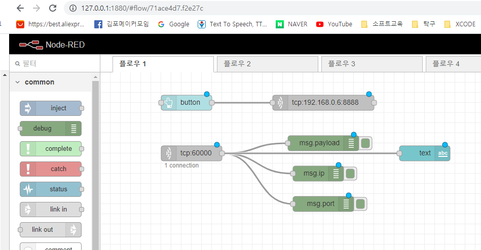
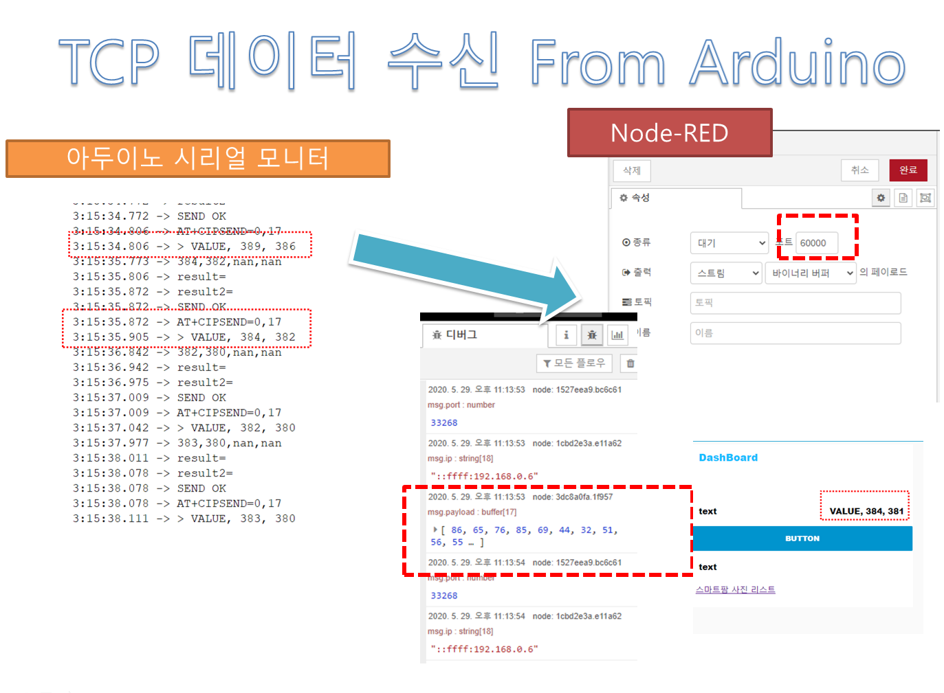
아두이노로부터 TCP 데이터를 수신합니다.
샘플 동영상
'Node-RED 우노빅보드 스마트팜 > 우노빅보드와 Node-RED 연동' 카테고리의 다른 글
| ESP8266 ESP-01 최신 펌웨어 업데이트 (0) | 2020.06.03 |
|---|---|
| 우노빅보드 스마트팜 동작 테스트 (0) | 2020.05.31 |
| Node-Red 대쉬보드로 UDP 데이터 송신 (0) | 2020.05.28 |
| ESP8266 연결 & 이더넷 동작 테스트 (1) | 2020.05.27 |
| NGINX webserver 설치 on Windows (1) | 2020.05.23 |


